In the following five postings, I will present photographs and explanations about the old Dutch mechanical lever frames.
In 2015, the Nederlandse Spoorwegen (Dutch Railways; NS) do no longer have a single semaphore or lever frame. However, in my vacation in August 2015, I visited the "Zud-Limburgse Stoomtrein-Maatschappij"—"South Limburg Steam Railway Company", abbreviated as ZLSM—in the utmost south of the Netherlands, which has lever frames and semaphores at two stations, namely a central signal box at Wijlre-Gulpen and a traffic bureau and two signal boxes at Simpelveld. Although the frames have been adapted somewhat for the requirements of the museum railway operation, they still exhibit many features of the old Dutch railway signalling principles and technology—which was, astonishingly, a rather peculiar mix of German, Austrian and British components! For all railway friends and especially signalling aficionados who want to look beyond the boundaries of their own country, I'll try to describe this interesting signalling world.
First and foremost, I would like to thank the signalmen at Simpelveld's post T and post I, who gave me the opportunity to take many photos and also helped me with some explanations about these frames!
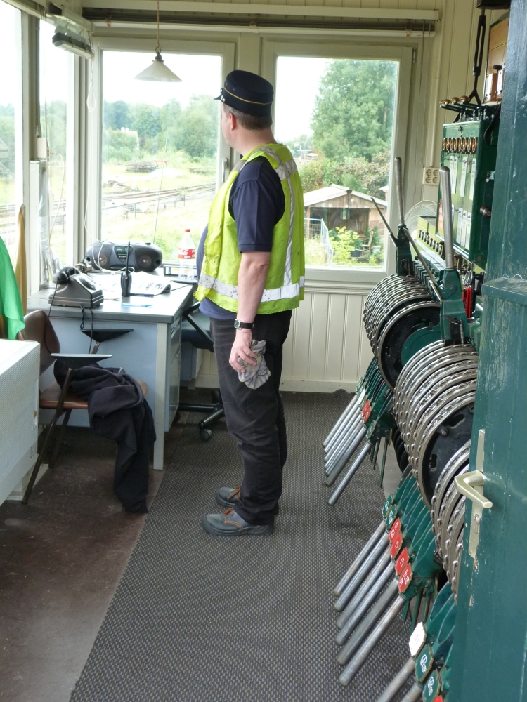
Signalman and lever frame, post I, Simpelveld, 17.8.2015
NS and its two predecessors, HSM and SS, were members of the "Union of German Railway Administrations" ("Verein deutscher Eisenbahnverwaltungen", VDEV"), which can be seen in this entry in Röll's railway encyclopedia of 1912 (my translation):
[The Union] encompassed from thereon the German Empire, the Austro-Hungarian Monarchy, the Kingdom of the Netherlands, the Grand Duchy of Luxembourg (and the Kingdom of Romania, which is no longer a member) as inner domain, whereas railway adminstrations whose lines are outside these countries form the outer domain. The following compilation shows the development of the union's network from 1880–1914:
But even though the Netherlands were tightly included in the VDEV, which was dominated by Germany's railways, especially Prussia, quite a number of technical and organisational features of Dutch signalling are distinctly "non-German," whereas others are genuinely "Central European." Here is my list of fourteen topics, which I will explain a little more in this and following postings with text, links, and pictures. For each topic, I have added my personal impression of the "signalling culture" that matches it best. Obviously, this is a somewhat subjective categorization—still, it should highlight my claim that Dutch signalling is an interesting crossover:

- a) Semaphores: Route signalling = "British"
- b) Responsibilities: Typically, train director with overall operations responsibility in station building + pointsmen in dependent signal boxes = "Austrian"
- c) Locking principles: Route locking = "Central European"
- d) Frames: very often "Siemens&Halske" frames—most often their frame type 3414 = "Austrian"; however, gripping the lever handles with a piece of cloth is distinctly "British"!
- e) Station block: Siemens block instruments, "German" version
- f) Block working: Siemens block instruments = "Central European"
- g) Coupling of station block and line block working: Decoupled = "German"
- h) Single line block working: permission per train = nearer to "Austrian" practice
- i) Locally operated points: with weighted levers = "Central European"
- j) Points: without blade locks = "British"
- k) Points: can
notbe run through = "Central European" - l) Working signals and points: by double wire, without tensioners = "Austrian"
- m) Slotting of signals: at signal = "British"
- n) Railway crossings: Barriers = "Central European", but often moved with levers = "British"
For researching Dutch semaphores and signal boxes, I mainly used the following websites—all of them are in Dutch, but with some knowledge in German and English and a dictionary the texts are quite easy to read:
- The first site is seinarm.nl, which explains semaphores and their positioning quite extensively.
- The second website is mainly about signal boxes and frames: http://www.klassiekebeveiliging.com/. An interesting page is this one, which shows interlocking at Simpelveld before the museum trains started.
- Third, www.nicospilt.com has, under "Seinreglementen" (signalling rules) some information and, additionally, a signalling rulebook from 1934.
- Last, but not least, there is some information about semaphores in the Dutch Wikipedia.
a) Semaphores: Route signalling = "British"
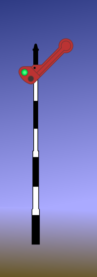
In principle, Dutch semaphore signalling was a route signalling system: At a station or branching, there was a separate semaphore for each track that could be reached (in contrast to that, the more modern light signals are a speed signalling system). Usually, cantilevers were user for placement of multiple arms for two or more routes. Additionally, there were signals with a single arm, used mainly as starting and block signals. However, as with most route signalling systems I know, a semaphore arm was often used to indicate entry into one of a group of tracks if these tracks were "sufficiently similar" (e.g., all tracks in a yard). The two sorts of signals ("simple signals" and "branching signals") were strictly distinguished in rules.
The following diagrams are from the Dutch Wikipedia entry about semaphores.
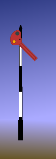
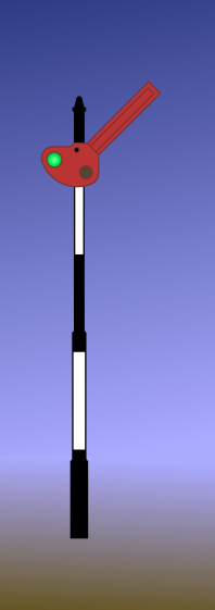
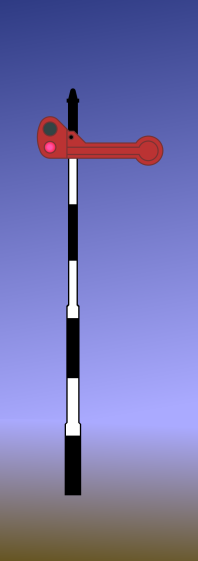
The simple distant and stop signals had a single arm. They could show the following aspects:
- Distant signal (voorsein): "onveilig" ("unsafe", "slow", i.e., the corresponding stop signal shows "stop!") with a lowered arm; and "veilig" ("safe", "clear", i.e., the corresponding stop signal shows "clear") with a raised arm:
- Stop signal (hoofdsein, "main signal"): "onveilig" ("unsafe", i.e., "stop!") with a horizontal arm; and "veilig" ("safe", i.e., "clear") with a raised arm:
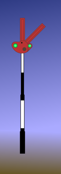
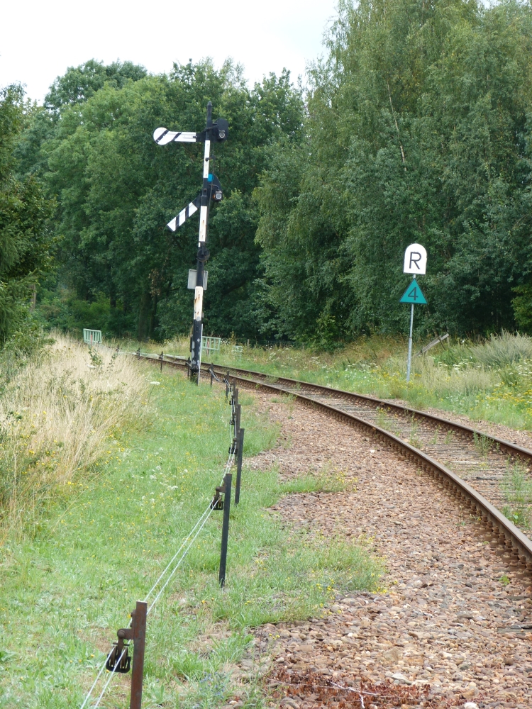
Here are the three eastern starting signals in Simpelveld:
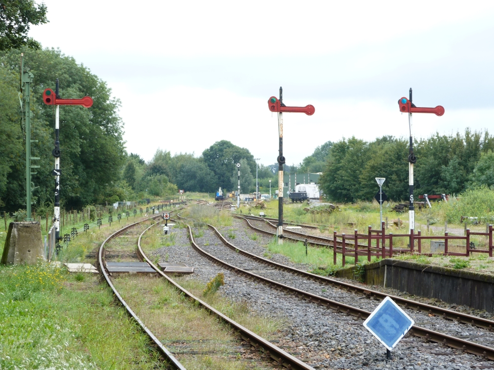
Starting signals C1, C2, and C3RK, 17.8.2015
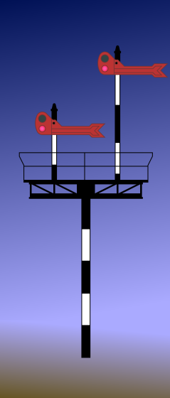
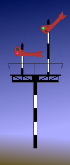
The following picture shows home signal D and corresponding distant signal Dv at Wijlre-Gulpen from the back side:
Home signal D and (far away) distant signal Dv at Wijlre-Gulpen, 17.8.2015
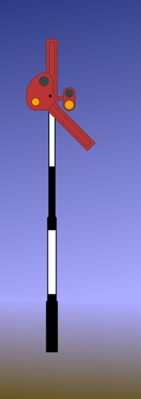
At station entries and branchings, multiple signal arms were mounted side by side on a cantilever. Such a branching signal had arms with fishtail cutouts in a slightly enlarged head. In a sort of attempt at speed signalling, the height of the arm was used to indicate whether the subsequent track could be travelled with maximum speed or with a reduced speed: The highly mounted arms indicated maximum speed, lower arms restricted the speed to 45 (or sometimes 40) kph. As indicated above, sometimes a single arm could signal a route into more than one track, if all tracks had similar speed restrictions. This is similar to Austrian (and, I assume, German) route signalling before 1930. At most, four arms were mounted beside each other. Here are the corresponding diagrams:
- Distant signal (voorsein): "onveilig" ("unsafe", i.e., all arms on the following branching signal cantilever show "stop!") with one lowered and one vertical arm; "veilig" ("safe", i.e., one of the branching signal arms for a route with maximum speed shows "clear") with one raised and one vertical arm; and "krom" ("branch", i.e., one of the branching signal arms for a route with restricted speed shows "clear") with one lowered and one raised arm:
- The stop signals (hoofdsein) show the same aspects as with simple signals, just using arms with fishtails cutouts:
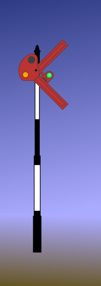
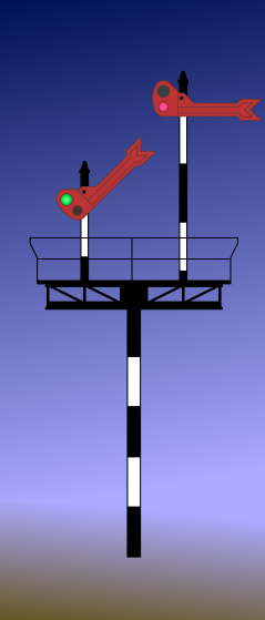
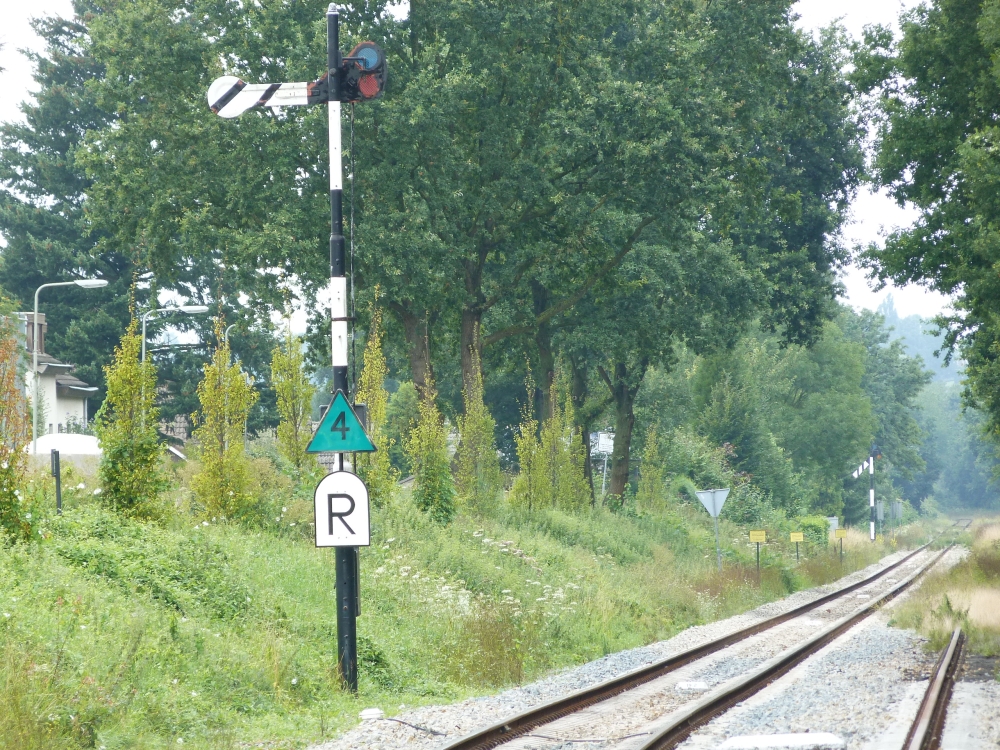
Home signals usually also had a distant arm for the start signal on the running track attached. Here is a photo of this combination from Simpelveld—unfortunately, I only took a picture from the back side:
Home signal B1-3 and distant signal Dv1 (for starter D1) from back side, Simpelveld, 17.8.2015
Around 1940, NS introduced speed signalling also with semaphores, in the following way:
In advance of a group of diverging tracks, it was now allowed to place a single-armed semaphore with a fishtail arm, whose upper half was red, whereas the lower half of the arm was white. The stop signal, however, did not indicate the speed restriction at all—only the corresponding distant signal would indicate "onveilig," "veilig," or "krom"—i.e., "caution," "clear," or "restricted." (A similar concept of signalling the expected speed only at the distant signal was used in Italy; and it is still used with signs for restricted speed zones, e.g. during works, in Germany and Austria). During nightfall, the single-armed branching signal would show a flashing green light (on a semaphore!). However, from 1942 onwards—i.e., in the middle of World War II—, the corresponding electrical circuits were deemed too expensive; instead, the arm was illuminated with an additional light.
Using these single-armed branching semaphores, the multiple signal heads at many smaller stations could be replaced with a single arm. But of course, many secondary lines did not have extensive route signalling at all, instead having only single-arm home signals, where the train crew had to understand via their time table whether they would travel into a loop or the through track. If a through train was to use a loop track, it would have to be "signalled down" at the home signal, and possibly be informed in writing at a previous station of the changed route.
Also Simpelveld and Wijlre-Gulpen have simple single-arm semaphores as home signals as well as distant signals, so that the underlying route signalling is not discernible. A last relict of route signalling is the symbol of two branch signal arms on the track diagram at post I (which I will show in a later posting) for leaving track 3 either towards Kerkrade or towards Germany. But the actual signal, as of today, is also a single-arm semaphore.
In addition to the semaphore type signals mentioned above, there were single-arm automatic block signals which showed "clear" unless the block ahead was occupied; and some branching signals with two round-headed arms mounted below each other. Some information about these signals can be found here at www.klassiekebeveiliging.com.
You can find pictures of original Dutch semaphores at these websites, among others:
b) Responsibilities: Typically, train director with overall operations responsibility in station building + pointsmen in dependent signal boxes = "Austrian"
The Dutch railways, as all Central European ones, have the concept of a "station" as a single unit with regards to operations (this is in contrast to English-speaking countries, where signal boxes essentially are independent operational units, irrespective of whether they are responsible for signals in the area of a single station or not. For more information about this distinction, please read Jörn Pachl's "German Block and Interlocking Principles – An Introduction for the foreign Reader"). Therefore, in the Netherlands, the responsibilities in a (larger) station are divided up between
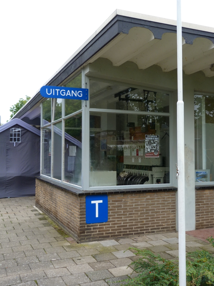
- the train director ("treindienstleider"), whose workplace is the traffic bureau ("post T"—the T is for "treindienstleider") in the station building;
- and the pointsmen in signal boxes, who are responsible for setting points and (stop and distant) signals according to the train director's orders (usually, given with block instruments or over telephone).
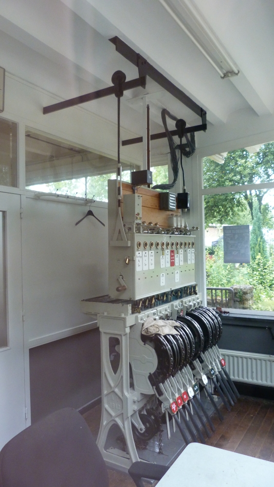
Post T (traffic bureau), Wijlre-Gulpen, 17.8.2015
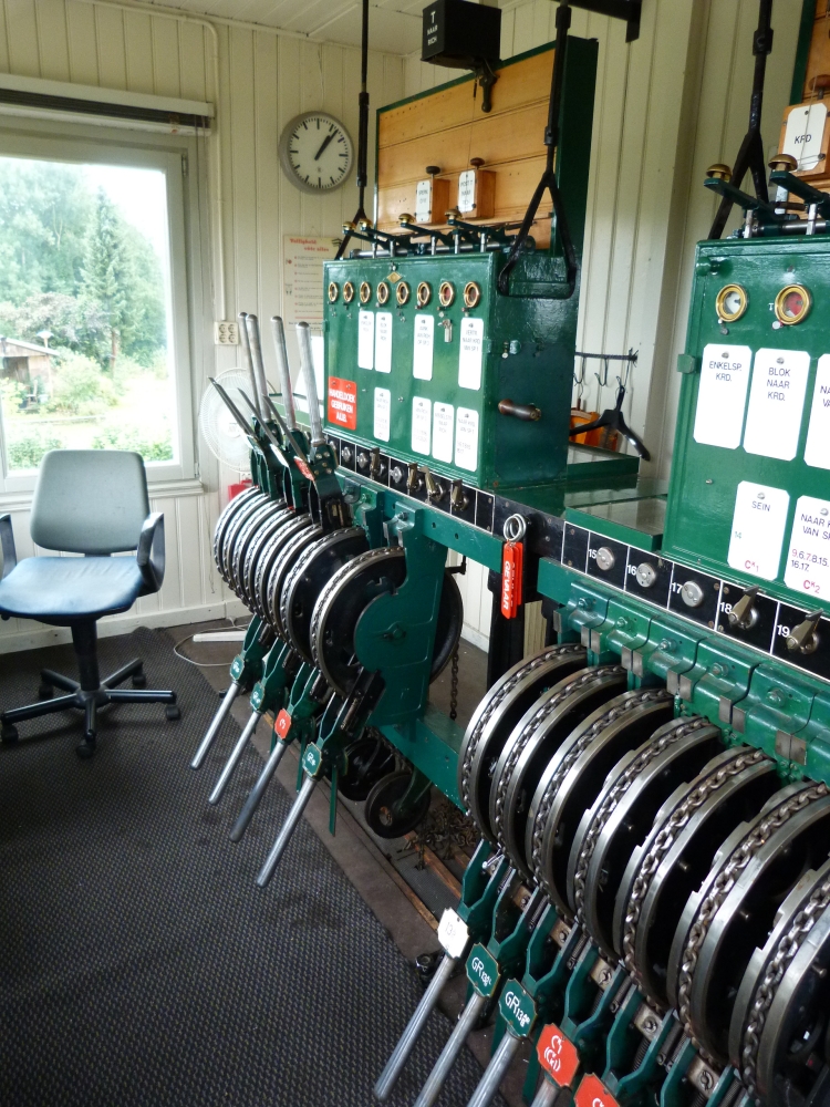
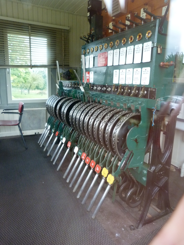
When a station is so large that its points and signals cannot be operated from a central "post T," it is necessary to set up signal boxes—typically, they are located at the station throats. In Dutch, these signal boxes are also called "posts," and they are numbered with Roman numerals. A larger station, therefore, has a "post T," a "post I," and a "post II." Simpelveld is such a station:
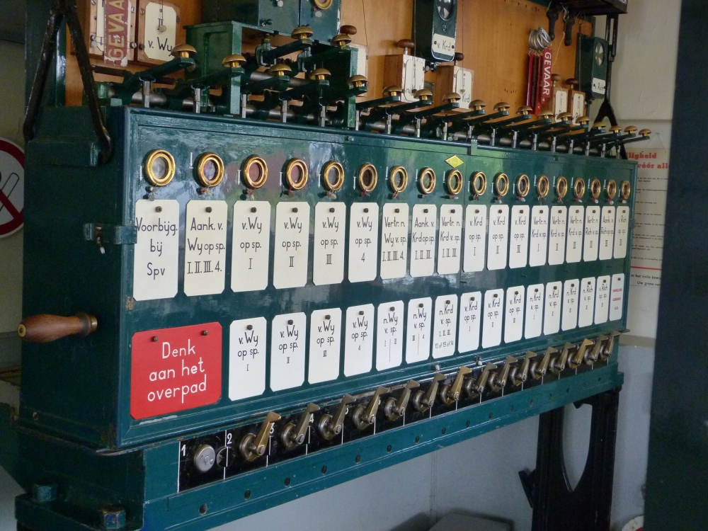
Block instruments at post T, Simpelveld, 17.8.2015
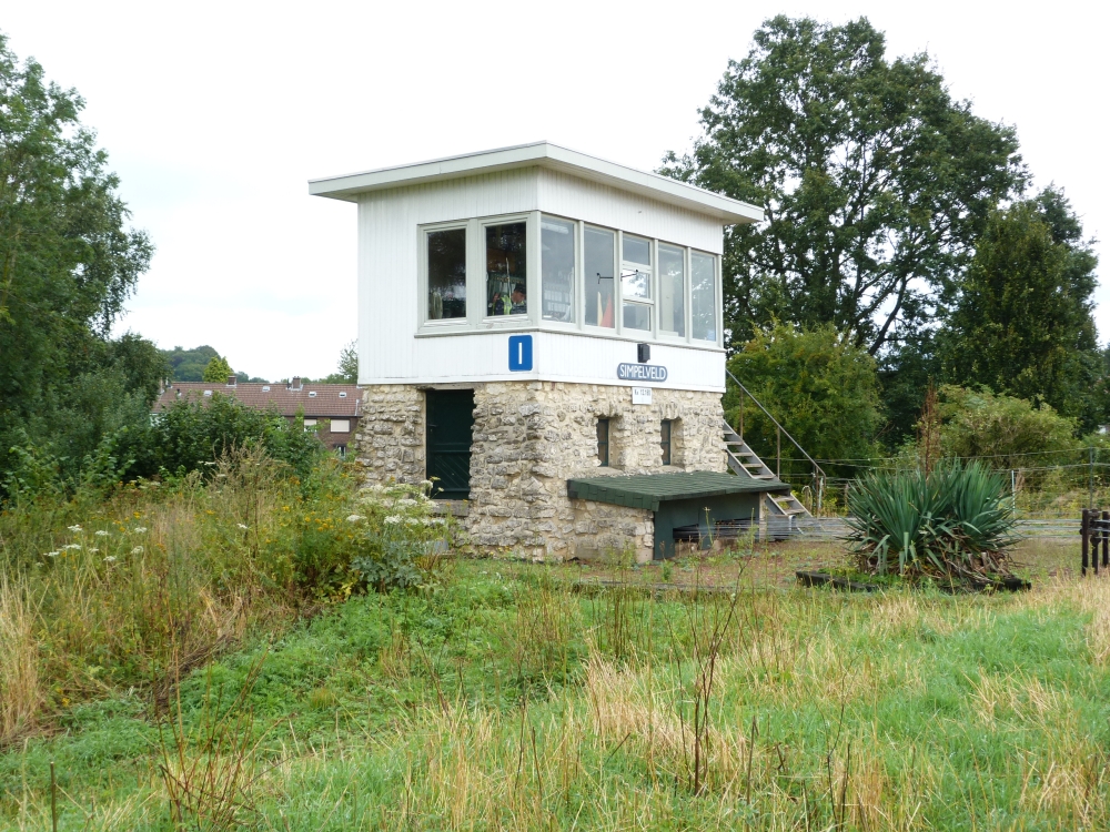
Post I, Simpelveld, 17.8.2015
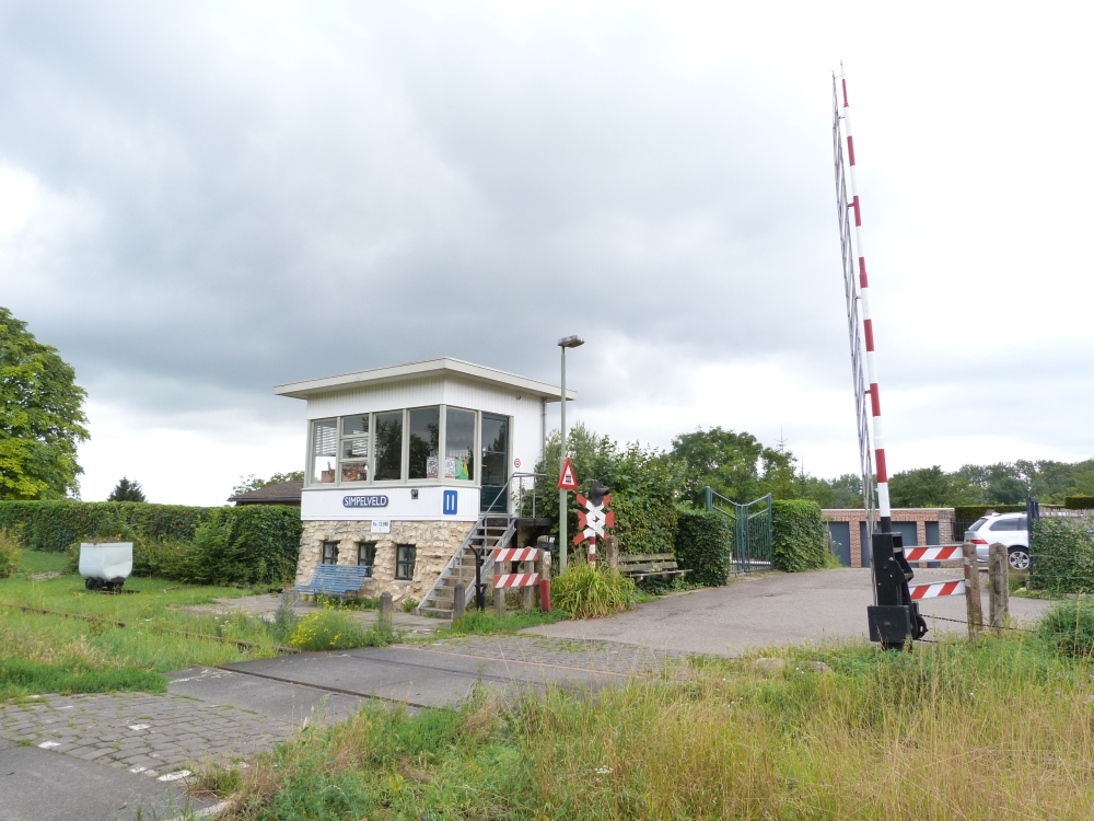
Post II, Simpelveld, 17.8.2015
c) Locking principles: Route locking = "Central European"
In English-speaking countries, interlocking frames use elements that lock levers directly with each other (in German, such locking is called "cascading interlocking," because when a route is set up, the locking effects are cascaded through the interlocking bed). The consequence of this is that interlocking is always operational, regardless of whether the levers are reversed for shunting or for through trains. Because of this, addition of shunting signals is not too expensive—almost no additional locking is needed for them, only the necessary levers and signals. Historically, therefore, British (and American) signal boxes have been equipped with shunting signals almost since their first uses in the 1860s.
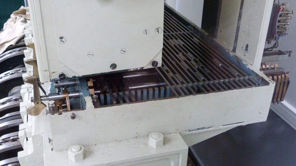
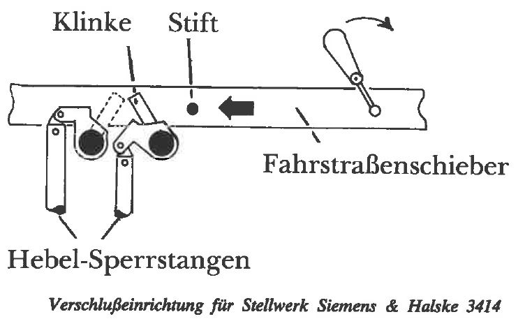
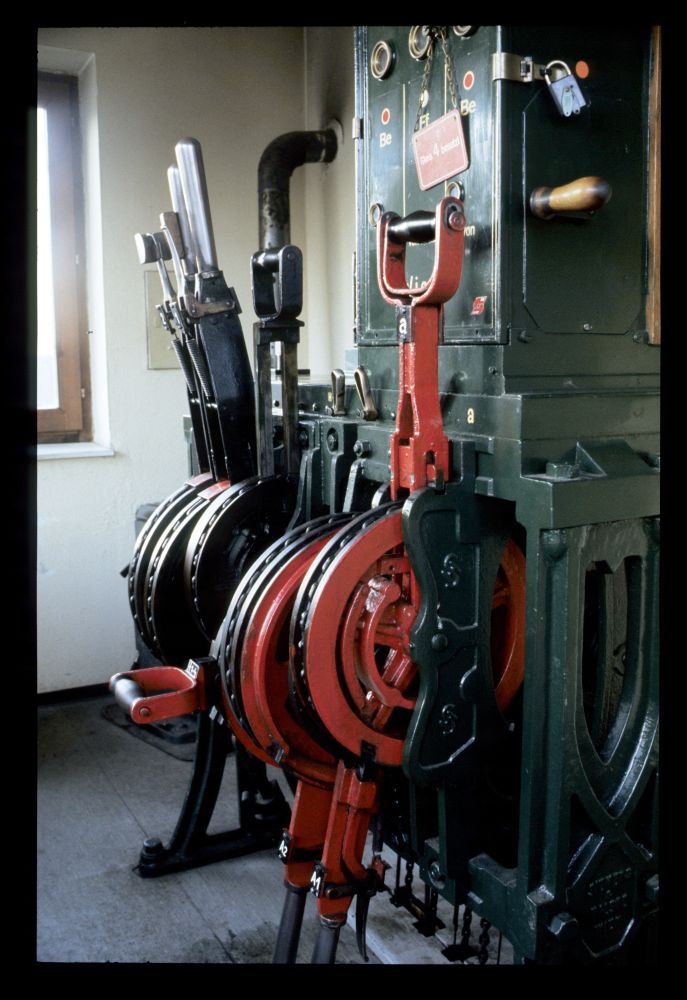
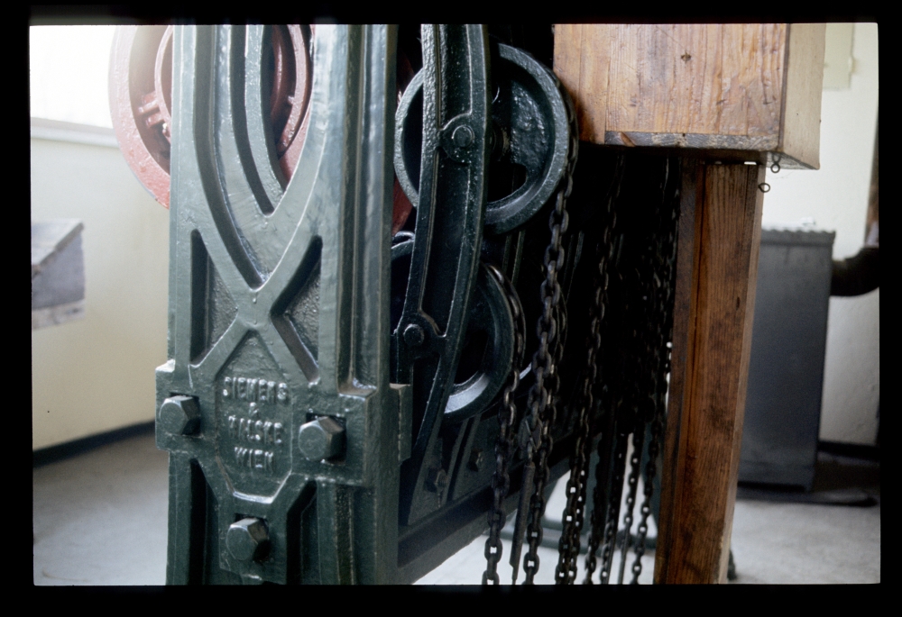
In contrast to this, Central European interlocking frames use freely reversible points levers without any locking facilities. Only when signals have to be cleared for a through train, the points levers are locked by special route bars. The reason for this is that initially and well into the 1880s and 1890s, all runs were over unsecured points, guarded by pointsmen (they also had to watch the station's signals, as these did not only convey information to the train crews, but also informed the pointsmen about train runs in their vicinity). When interlocking frames started to be installed, the practice that shunting was done without locked points was continued, whereas points under through trains had to be locked. This locking was done by locking the corresponding levers with route bars, which were installed from 1872 onwards in interlocking frames by Siemens&Halske and Büssing. Protecting trains by route locking has been standard since then for all mechanical and electromechanical frames in Central Europe.
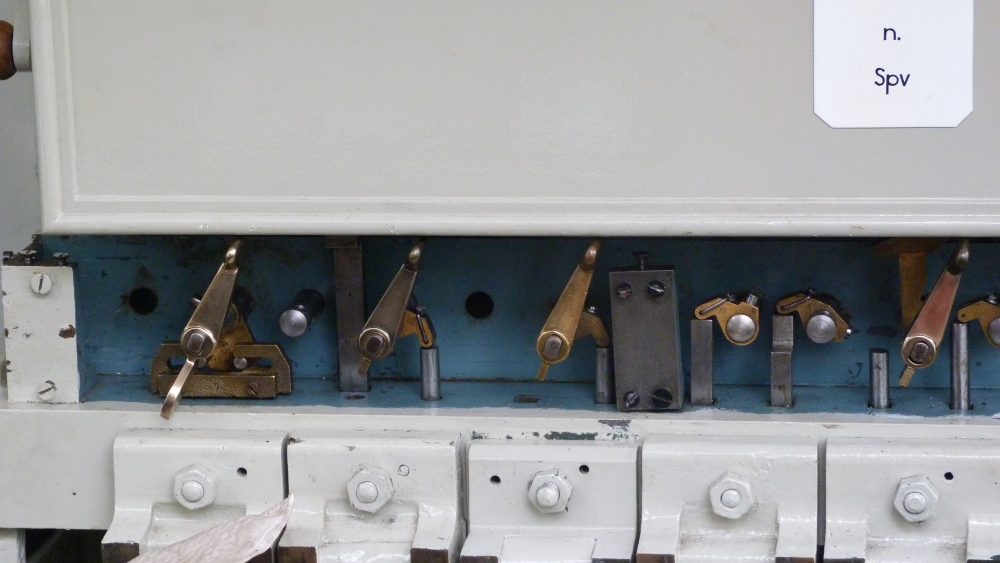
Here is the interlocking frame at Wijlre-Gulpen, which has been modified for demonstrational purposes such that the route bars can be seen:
Route bars in interlocking frame, post T, Wijlre-Gulpen, 17.8.2015
At Simpelveld, the route bars move under glass covers:
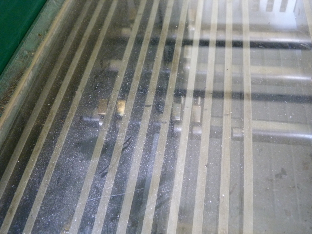
Route bars in interlocking frame, post I, Simpelveld, 17.8.2015
d) Frame types: (among others) "Siemens&Halske" type 3414 = "Austrian"
According to www.klassiekebeveiliging.com ("Voorschriften voor de bediening van wissel- en seininrichtingen—Deel IV—Mechanische bedieningstoestellen"), lever frames in the Netherlands were mainly provided by the following companies:
- Alkmaarsche Metaal- en IJzergieterij (Alkmaar metal and iron foundry)
- Siemens&Halske
- 3414
- 3500
- 3500a ("Romanian type")
- 3500c (better known as type 5007, which was its number in the Austrian ministry's of railways plans from 1909).
- and also the older type 12SA.
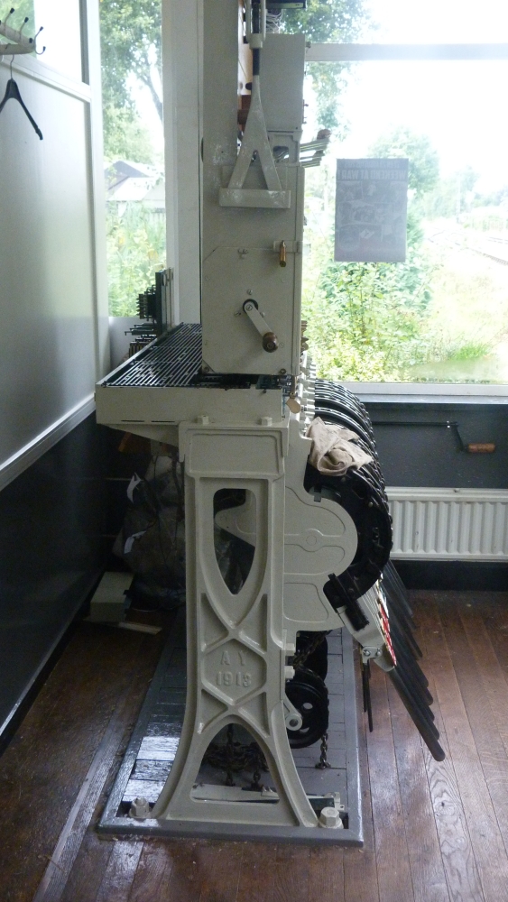
One can study the typical 3414 features more closely on the frame at Wijlre-Gulpen, which has been modified by ZLSM as an demonstration frame with open locking bed (or rather "route bar bed"). Here is a detail that shows the mechanics between the levers and the locking bed, and a second picture of the frame's left side with the typical "curved X" of the 3414 frame:
Interlocking frame, post T, Wijlre-Gulpen, 16.8.2015
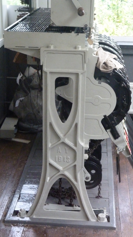
Interlocking frame, post T, Wijlre-Gulpen, 16.8.2015
For comparison, here are two excerpts from 3414 diagrams from the standard book about Austrian interlocking frames, "Eisenbahnsicherungsanlagen in Österreich" by Christian Hager:
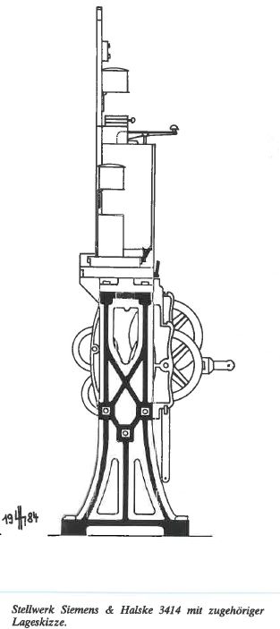
For interested readers, I have scanned the two pages in that book that deal with type 3414 frames (a click on the image opens a readable—German—PDF file):

Interestingly, Siemens also installed some 3414 frames in Germany, mainly on some lines near Berlin, as can be seen on this page about signal boxes in and around Berlin. This fact is unknown to most German signalling aficionados, and in fact was also unknown to a manager of the German Reichsbahn of the GDR, as is explained in a story on that page.
Additionally, 3414 frames were also present in other countries that formerly were part of Austria-Hungary. At present, I only know of one signal box with a 3414 which is in Becov nad Teplou in Czechia. This box and its frame is presented on this website.
Back to the Netherlands: As mentioned, most 3414 frames there were not built by Siemens, but by Alkmaar. The frame at Wijlre-Gulpen shows the abbreviation "AY" (and the year 1913) on its side, which points to the Alkmaar factory—however, "AY" is, as far as I gather, a genuine Alkmaar type, so that it is unclear (to me) why it was present on this Siemens type frame.
For further comparison, here are some more pictures of the frames at Wijlre-Gulpen and Simpelveld (from 2015) and the last Austrian 3414 with points levers at Frättingsdorf (from 1987):
Interlocking frame, post T, Wijlre-Gulpen, 16.8.2015
Interlocking frame, post I, Simpelveld, 16.8.2015
Interlocking frame, post II, Simpelveld, 16.8.2015
Interlocking frame, signal box 1, Frättingsdorf, March 1987
Interlocking frame, post T, Wijlre-Gulpen, 16.8.2015
Interlocking frame, signal box 1, Frättingsdorf, March 1987
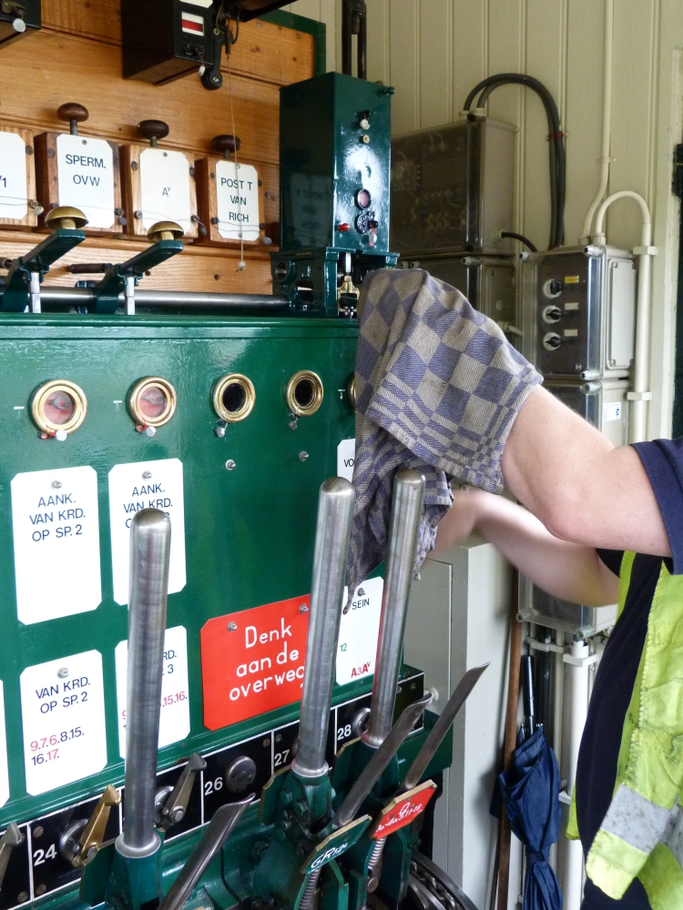
After all this talk about the "Austrian-ness" of Dutch frames, I have to add one aspect of them which is genuinely British: As is the case there, the shiny handles of the levers are never touched with bare hands (as it is customary in Austria and Germany), but only with an intermediate piece of cloth:
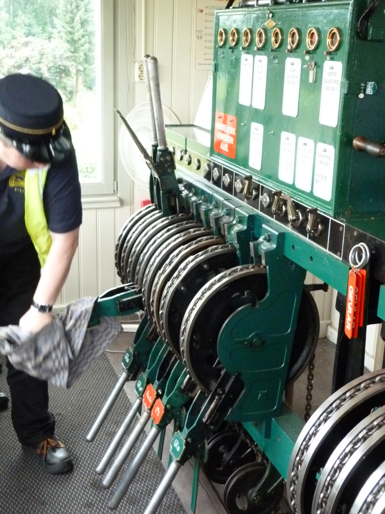
Reversing a lever, post II, Simpelveld, 16.8.2015
And even the handles of block instruments are pressed down with that piece of cloth:
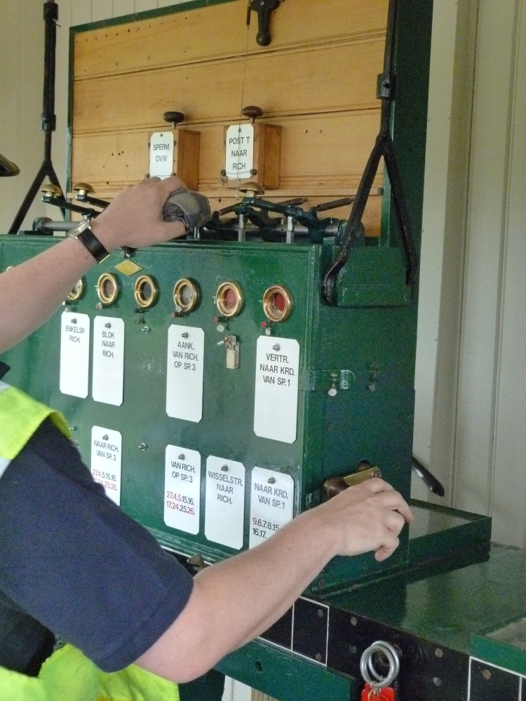
Blocking a block instrument, post II, Simpelveld, 16.8.2015
Blocking a block instrument, post II, Simpelveld, 16.8.2015
This is the end of my first posting about Dutch lever frames. The next posting will contain more photos (and not so many explanations), after that I will continue with comments about the fourteen topics mentioned at the beginning.
No comments:
Post a Comment